LABORATORY: CNR ISPC – XRAYLab
NAME OF THE INSTRUMENT
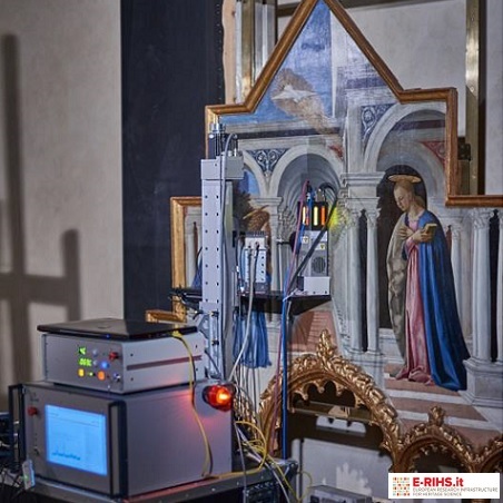
XRD imaging scanner developed by XRAYLab
GENERAL DESCRIPTION
X-ray diffraction (XRD) allows determining the mineralogical phases characterizing the materials under study. Unlike elemental analytical techniques such as the XRF technique, the XRD technique provides information on the nature of chemical compounds (even in complex mixtures) and their structure. Given the crystalline nature of different types of ancient materials, the XRD technique is particularly suitable for the analysis of archaeological and historical-artistic samples and their degradation products. The main limitation of the XRD technique generally applied in situ or in the laboratory is to be punctual and to provide only local information. ISPC's XRAYlab laboratory recently developed an innovative mobile XRD imaging system capable of providing images of the distribution of crystalline phases on macroscopic samples. This information is crucial for a better knowledge of materials and manufacturing techniques and for the study of degradation processes
The mobile XRD mapping system developed by ISPC's XRAYLab operates the diffraction of polycrystalline samples in grazing geometry and parallel rays with the advantage of keeping the X source, detector and sample fixed and without the need for angular scanning of the Bragg angles.
This experimental setup allows obtaining accurate XRD patterns, less affected by angular shifts and a higher resolution. The technique is non-invasive, and no sample preparation is required.
TECHNICAL DESCRIPTION
The XRD imaging system developed by ISPC's XRAYLab laboratory is a mobile system optimized to operate was designed and built to meet the need not to move the works from the place where they are stored. The system consists of 3 XYZ linear axes with a stroke of 50x50x20cm on which the XRD / XRF measurement is mounted. This is equipped with a 30W X microfocus source with Cu anode coupled to a polycapillary optic collimated with a rectangular slide. The dimensions of the beam at the measuring point are 0.2x1mm. The detection of the diffraction pattern diffused by the samples takes place using a Si-strip detector sensitive to position and energy that covers an angular range from 15 to 60 degrees in 2theta. During the measurements it is possible to simultaneously acquire the XRD pattern and the XRF spectrum for the same measurement point. This mode is obtained by means of an ancillary SDD detector for XRF always positioned on the measuring head and which operates in parallel, by means of dedicated electronics, to the Si-strip diffraction detector. Finally, on the measuring head there is a laser sensor that monitors the distance of the beam from the sample moment by moment and dynamically corrects the position following the morphology of the surface under examination. XRD / XRF measurements take place through a ste-by-step scan (maximum air 50x50cm) with an acquisition time per step equal to 1s. The analysis of XRD and XRF data and the production of images of the distribution of the phases (XRD) and of the elements (XRF) takes place using proprietary software programmed on the system.
Referent:
Paolo Romano francescopaolo.romano@cnr.it
